Unless otherwise noted, credit for pinout images and information from Pinouts.ru - every connector type links back to corresponding Pinouts.ru page
BNC

Image credit to Thor Labs
Balanced Mono
| 1 |
In Phase/Hot |
| 2 |
Out of Phase/Cold |
| 3 |
Ground |
Unbalanced Stereo
| 1 |
Signal (Left Channel) |
| 2 |
Signal (Right Channel) |
| 3 |
Ground |
Balanced Audio
| 1 |
Ground |
| 2 |
In Phase/Hot |
| 3 |
Out of phase/Cold |
AES/EBU
| 1 |
Ground |
| 2 |
Data (Channel 1) |
| 3 |
Data (Channel 2) |
S-Video
| 1 |
Ground (Y) |
| 2 |
Ground (C) |
| 3 |
Luminance (Y) |
| 4 |
Chrominance (C) |
Apple Desktop Bus
| 1 |
ADB bidirectional data |
| 2 |
Power switch |
| 3 |
Power +5V |
| 4 |
Ground |
Unbalanced Audio
| 1 |
Signal Input (Left channel) |
| 2 |
Ground |
| 3 |
Signal Output (Left channel) |
| 4 |
Signal Input (Right channel) |
| 5 |
Signal Output (Right channel) |
MIDI
| 1 |
Not connected |
| 2 |
Shield (input)/Ground (output) |
| 3 |
Not connected |
| 4 |
Signal (source on input, sink on output) |
| 5 |
Signal (sink on input, source on output) |
PS/2
| 1 |
Key data (keyboard), Button/Position data (mouse) |
| 2 |
not connected |
| 3 |
Ground |
| 4 |
Power, +5V |
| 5 |
Clock |
| 6 |
not connected |
Image credit to captain18 at LiveJournal
| 1 |
Ground |
| 2 |
Transmit+ (data) |
| 3 |
Transmit- (data) |
| 4 |
Ground |
| 5 |
Receive+ (data) |
| 6 |
Receive- (data) |
| 7 |
Ground |
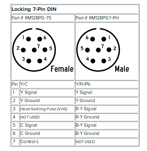
 Image credit to Lab Guy's World
| 1 |
Audio out |
| 2 |
Video out |
| 3 |
Video in |
| 4 |
Video in |
| 5 |
Audio out |
| 6 |
Video out |
| 7 |
Audio in |
| 8 |
Audio in |
Apple RS-422
| 1 |
Output Handshake |
| 2 |
Input Handshake or External Clock |
| 3 |
Transmit- (data) |
| 4 |
Ground |
| 5 |
Receive data- (data) |
| 6 |
Transmit data+ (data) |
| 7 |
General Purpose Input |
| 8 |
Receive data- (data) |
RS-232
| 1 |
Carrier detect |
| 2 |
Receive data |
| 3 |
Transmit data |
| 4 |
Data terminal ready |
| 5 |
Ground |
| 6 |
Data set ready |
| 7 |
Request to send |
| 8 |
Clear to send |
| 9 |
Ring indicator |
Sony 9-pin RS-422 VTR protocol
| 1 |
Frame ground |
| 2 |
Transmit A |
| 3 |
Receive B |
| 4 |
Receive common |
| 5 |
spare/ground |
| 6 |
Transmit common |
| 7 |
Transmit B |
| 8 |
Receive A |
| 9 |
Frame ground |
| 1 |
Ground |
Ground |
| 2 |
Vertical Sync |
not used |
| 3 |
Horizontal Sync |
not used |
| 4 |
Red return |
Ground |
| 5 |
Red video |
S-Video Chroma (C) |
| 6 |
Green return |
Ground |
| 7 |
Green video |
S-Video Luma (Y) |
| 8 |
Power +5V |
Power +5V |
| 9 |
Blue video |
Composite video |
| 10 |
DDC data |
DDC data |
| 11 |
DDC clock |
DDC clock |
| 12 |
Ground |
| 13 |
Cable detect |
Cable detect |
| 14 |
Blue return |
Ground |
| 1 |
+5v |
Power |
| 2 |
A Right Button |
Joystick/A Right Button |
| 3 |
A / X-position |
Joystick/A X-Coordinate |
| 4 |
Signal GND |
Ground |
| 5 |
Signal GND |
Ground |
| 6 |
A / Y-position |
Joystick/A Y-Coordinate |
| 7 |
A Left Button |
Joystick/A Left Button |
| 8 |
+5v |
Power |
| 9 |
+5v |
Power |
| 10 |
B Right Button |
Joystick/B Right Button |
| 11 |
B / X-position |
Joystick/B X-Coordinate |
| 12 |
MIDI Out |
MIDI Output |
| 13 |
B / Y-position |
Joystick/B Y-Coordinate |
| 14 |
B Left Button |
Joystick/B Left Button |
| 15 |
MIDI In |
MIDI Input |
DA-15 had highly varied pinouts depending on the specific peripheral in question. See pinouts.ru for more options.
VGA
| 1 |
Red video |
| 2 |
Green video |
| 3 |
Blue video |
| 4 |
reserved |
| 5 |
Ground |
| 6 |
Red ground |
| 7 |
Green ground |
| 8 |
Blue ground |
| 9 |
Key (no pin)/Optional +5V power output |
| 10 |
Sync ground |
| 11 |
Monitor ID Bit 0 (optional) |
| 12 |
I2C bidirectional data |
| 13 |
Horizontal Sync |
| 14 |
Vertical Sync |
| 15 |
I2C data clock |
USB 2.0


| 1 |
Power +5V |
Power +5V |
Power +5V |
| 2 |
Data - |
Data - |
Data - |
| 3 |
Data + |
Data + |
Data + |
| 4 |
Ground |
Ground/Attached device indicator/not connected |
Ground/attached device indicator/ground |
| 5 |
|
Ground |
Ground |
USB 3.0


| 1 |
Power +5V |
Power +5V |
Power +5V |
Power +5V |
| 2 |
Data - (2.0 speed) |
Data - (2.0 speed) |
Data - (2.0 speed) |
Data - (2.0 speed) |
| 3 |
Data + (2.0 speed) |
Data + (2.0 speed) |
Data + (2.0 speed) |
Data + (2.0 speed) |
| 4 |
Ground (power) |
Ground (power) |
Ground (power) |
ID configuration line |
| 5 |
RX- (Superspeed receiver) |
TX- |
TX- |
Ground |
| 6 |
RX+ (Superspeed receiver) |
TX+ |
TX+ |
TX- |
| 7 |
Ground (signal) |
Ground (signal) |
Ground (signal) |
TX+ |
| 8 |
TX- (Superspeed transmitter) |
RX- |
RX- |
Ground |
| 9 |
TX+ (Superspeed transmitter) |
RX+ |
RX+ |
RX- |
| 10 |
|
|
Power provided by device |
RX+ |
| 11 |
|
|
Ground for power provided by device |
|
USB 3.1
| A1 |
Ground |
| A2 |
TX1+ (Superspeed transmitter) |
| A3 |
TX1- (Superspeed transmitter) |
| A4 |
Power |
| A5 |
CC1 (orientation configuration information) |
| A6 |
Data+ (2.0 speed) |
| A7 |
Data- (2.0 speed) |
| A8 |
Secondary bus 1 |
| A9 |
Power |
| A10 |
RX2- (Superspeed receiver) |
| A11 |
RX2+ (Superspeed receiver) |
| A12 |
Ground |
| B1 |
Ground |
| B2 |
TX2+ (Superspeed transmitter) |
| B3 |
TX2- (Superspeed transmitter) |
| B4 |
Power |
| B5 |
CC2 (orientation configuration information) |
| B6 |
Data+ (2.0 speed) |
| B7 |
Data- (2.0 speed) |
| B8 |
Secondary bus 2 |
| B9 |
power |
| B10 |
RX1- (Superspeed receiver) |
| B11 |
RX1+ (Superspeed receiver) |
| B12 |
Ground |
4-pin
| 1 |
Twisted-Pair B- (data) |
| 2 |
Twisted-Pair B+ (data) |
| 3 |
Twisted-Pair A- (data) |
| 4 |
Twisted-Pair A+ (data) |
6-pin
| 1 |
Power |
| 2 |
Ground |
| 3 |
Twisted-Pair B- (data) |
| 4 |
Twisted-Pair B+ (data) |
| 5 |
Twisted-Pair A- (data) |
| 6 |
Twisted-Pair A+ (data) |
9-pin
| 1 |
Twisted-Pair B- (data) |
| 2 |
Twisted-Pair B+ (data) |
| 3 |
Twisted-Pair A- (data) |
| 4 |
Twisted-Pair A+ (data) |
| 5 |
A shield |
| 6 |
Ground |
| 7 |
not used |
| 8 |
Power |
| 9 |
B shield |
| 1 |
Data 2+ |
| 2 |
Data 2- |
| 3 |
Data 1 + |
| 4 |
Data 1 - |
| 5 |
Data 0 + |
| 6 |
Data 0 - |
| 7 |
Clock + |
| 8 |
Clock - |
| 9, 10, 11, 12, 13, 14, 15, 16 |
Digital Signal Ground |
| 17 |
Power +5V |
| 18 |
DCC data |
| 19 |
not used |
| 20 |
Analog Blue |
| 22 |
Analog Green |
| 21, 23 |
not used |
| 24 |
Analog Red |
| 25 |
Detect |
| 26 |
DCC clock |
| 27 |
not used |
| 28, 30, 32 |
Digital Signal Ground |
| 29 |
Analog Horizontal Sync |
| 31 |
Analog Vertical Sync |
| 1 |
Data 2- |
| 2 |
Data 2+ |
| 3 |
Data 2/4 shield |
| 4 |
Data 4- |
| 5 |
Data 4+ |
| 6 |
DDC clock |
| 7 |
DDC data |
| 8 |
Analog Vertical Sync |
| 9 |
Data 1- |
| 10 |
Data 1+ |
| 11 |
Data 1/3 shield |
| 12 |
Data 3- |
| 13 |
Data 3+ |
| 14 |
Power +5V |
| 15 |
Ground |
| 16 |
Detect |
| 17 |
Data 0- |
| 18 |
Data 0+ |
| 19 |
Data 0/5 shield |
| 20 |
Data 5- |
| 21 |
Data 5+ |
| 22 |
Clock shield |
| 23 |
Clock + |
| 24 |
Clock - |
| C1 |
Analog Red |
| C2 |
Analog Green |
| C3 |
Analog Blue |
| C4 |
Analog Horizontal Sync |
| C5 |
Analog Ground |


| 1 |
Main Lane 0+ (data) |
Ground |
| 2 |
Ground |
Detect |
| 3 |
Main Lane 0- (data) |
Main Lane 0- (data) |
| 4 |
Main Lane 1+ (data) |
Ground |
| 5 |
Ground |
Main Lane 0+ (data) |
| 6 |
Main Lane 1- (data) |
Ground |
| 7 |
Main Lane 2+ (data) |
Ground |
| 8 |
Ground |
Ground |
| 9 |
Main Lane 2- (data) |
Main Lane 1+ (data) |
| 10 |
Main Lane 3+ (data) |
Main Lane 3+ (data) |
| 11 |
Ground |
Main Lane 1- (data) |
| 12 |
Main Lane 3- (data) |
Main Lane 3- (data) |
| 13 |
Ground |
Ground |
| 14 |
Ground |
Ground |
| 15 |
Auxiliary Channel + |
Main Lane 2+ (data) |
| 16 |
Ground |
Auxiliary Channel + |
| 17 |
Auxiliary Channel - |
Main Lane 2- (data) |
| 18 |
Detect |
Auxiliary Channel - |
| 19 |
Return for Power |
Ground |
| 20 |
Power |
Power |


| 1 |
Data2 + |
Data2 shield |
detect |
| 2 |
Data2 shield |
Data2 + |
not connected |
| 3 |
Data2 - |
Data2 - |
Data2 + |
| 4 |
Data1 + |
Data1 shield |
Data2 shield |
| 5 |
Data1 shield |
Data1 + |
Data2 - |
| 6 |
Data1 - |
Data1 - |
Data1 + |
| 7 |
Data0 + |
Data0 shield |
Data1 shield |
| 8 |
Data0 shield |
Data0 + |
Data1 - |
| 9 |
Data0 - |
Data0 - |
Data0 + |
| 10 |
Clock + |
Clock shield |
Data0 shield |
| 11 |
Clock shield |
Clock + |
Data0 - |
| 12 |
Clock - |
Clock - |
Clock + |
| 13 |
control |
DDC ground |
Clock shield |
| 14 |
not connected |
control |
Clock - |
| 15 |
DDC clock |
DDC clock |
control |
| 16 |
DDC data |
DDC data |
DDC ground |
| 17 |
DDC ground |
HEC+/not connected |
DDC clock |
| 18 |
Power +5V |
Power +5V |
DDC data |
| 19 |
detect |
HEC-/not connected |
Power +5V |
| 1 |
Audio Out right |
| 2 |
Audio In right |
| 3 |
Audio Out left (+ Mono) |
| 4 |
Audio Ground |
| 5 |
RGB Blue ground |
| 6 |
Audio In left (+ Mono) |
| 7 |
RGB Blue in |
| 8 |
Switch control (Audio/RGB) |
| 9 |
RGB Green ground |
| 10 |
Clockpulse out |
| 11 |
RGB Green in |
| 12 |
Data out |
| 13 |
RGB Red ground |
| 14 |
Data ground |
| 15 |
RGB Red in/S-Video Chroma (C) |
| 16 |
Blanking signal |
| 17 |
Composite Video ground or S-Video Luma ground |
| 18 |
Blanking signal ground |
| 19 |
Composite video out |
| 20 |
Composite video in / S-Video Luma / RGB Sync |
| 21 |
Ground/shield (chassis) |
Parallel SCSI
| 1 |
Request |
| 2 |
Message |
| 3 |
Input/Output |
| 4 |
Reset |
| 5 |
Acknowledge |
| 6 |
Busy |
| 7 |
not used |
| 8 |
Data Bus 0 |
| 9 |
not used |
| 10 |
Data Bus 3 |
| 11 |
Data Bus 5 |
| 12 |
Data Bus 6 |
| 13 |
Data Bus 7 |
| 14 |
not used |
| 15 |
Control |
| 16 |
not used |
| 17 |
Attention |
| 18 |
not used |
| 19 |
Select |
| 20 |
Data Parity |
| 21 |
Data Bus 1 |
| 22 |
Data Bus 2 |
| 23 |
Data Bus 4 |
| 24 |
not used |
| 25 |
Termination Power |
Parallel/Printer Port
| 1 |
Strobe |
| 2 |
Data Bit 0 |
| 3 |
Data Bit 1 |
| 4 |
Data Bit 2 |
| 5 |
Data Bit 3 |
| 6 |
Data Bit 4 |
| 7 |
Data Bit 5 |
| 8 |
Data Bit 6 |
| 9 |
Data Bit 7 |
| 10 |
Acknowledge |
| 11 |
Busy |
| 12 |
Paper Out |
| 13 |
Select |
| 14 |
Autofeed |
| 15 |
Error |
| 16 |
Reset |
| 17 |
Select |
| 18 |
Signal Ground |
| 19 |
Signal Ground |
| 20 |
Signal Ground |
| 21 |
Signal Ground |
| 22 |
Signal Ground |
| 23 |
Signal Ground |
| 24 |
Signal Ground |
| 25 |
Signal Ground |
Serial RS-232 Devices
RS-232 serial device pinouts could vary wildly depending on the specific device in question. Consult pinouts.ru for examples.